Ultimate Precision: The HEIGHT MASTER 515 Series Guide
Establishing precise reference heights on surface plates presents daily challenges for metrology labs. Wringing individual gauge blocks together takes valuable time and introduces stacking errors. The HEIGHT MASTER 515 series solves this issue by offering a rigid, staggered block stack for fast height setting and tool calibration.
This guide explores how this master standard elevates accuracy across quality control facilities.
What Is the HEIGHT MASTER 515 Series?
The 515 series is a high-precision reference instrument manufactured by Mitutoyo.
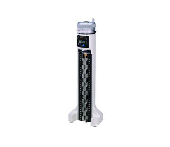
Featuring a rigid column of permanently stacked gauge blocks, this tool moves vertically via a micrometer head. Technicians use the top and bottom surfaces of the staggered blocks to set height gauges, calibrate bore gages, and inspect machined components instantly.
Key Advantages for Quality Control
Integrating a 515 series master into your calibration room delivers clear technical benefits:
High Reference Accuracy: Delivers sub-micron block accuracy down to 0.001 mm or 0.00005 inches.
Dual-Direction Reference: Provides reference surfaces on both top and bottom block faces without flipping the column.
Fast Height Setting: Replaces individual gauge block stacks to speed up tool setting cycles significantly.
Counter and Digital Display: Features clear mechanical counters or digital displays to eliminate micrometer reading errors.
Common Metrology Applications
Calibration technicians and quality inspectors rely on the 515 series for essential verification tasks:
Height Gauge Calibration: Verify electronic and mechanical height gauges across full travel ranges.
Surface Plate Inspection: Transfer precise reference height dimensions to workpieces using dial indicators.
Routine ISO Audits: Maintain strict measurement traceability needed for ISO quality compliance audits.
How to Set Reference Heights in 4 Steps
Follow these simple steps to obtain accurate reference measurements:
Clean the Base: Wipe the cast iron base and surface plate using alcohol and lint-free cloths.
Thermal Equalization: Allow the unit to acclimate to your room temperature before testing.
Adjust the Micrometer Head: Rotate the top micrometer thimble to your desired height setting.
Zero Your Indicator: Touch your measuring probe to the block face and zero your gauge.
Final Thoughts
The HEIGHT MASTER 515 series converts complex height setting routines into simple, repeatable tasks. By securing reliable reference standards, this durable instrument protects product quality across your manufacturing facility.
Height reference instrument
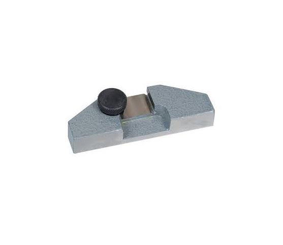
Rsier blcok is avaliable as optional
Ultimate Precision: The HEIGHT MASTER 515 Series Guide
Establishing precise reference heights on surface plates presents daily challenges for metrology labs. Wringing individual gauge blocks together takes valuable time and introduces stacking errors. The HEIGHT MASTER 515 series solves this issue by offering a rigid, staggered block stack for fast height setting and tool calibration.
This guide explores how this master standard elevates accuracy across quality control facilities.
What Is the HEIGHT MASTER 515 Series?
The 515 series is a high-precision reference instrument manufactured by Mitutoyo.
Featuring a rigid column of permanently stacked gauge blocks, this tool moves vertically via a micrometer head. Technicians use the top and bottom surfaces of the staggered blocks to set height gauges, calibrate bore gages, and inspect machined components instantly.
Key Advantages for Quality Control
Integrating a 515 series master into your calibration room delivers clear technical benefits:
High Reference Accuracy: Delivers sub-micron block accuracy down to 0.001 mm or 0.00005 inches.
Dual-Direction Reference: Provides reference surfaces on both top and bottom block faces without flipping the column.
Fast Height Setting: Replaces individual gauge block stacks to speed up tool setting cycles significantly.
Counter and Digital Display: Features clear mechanical counters or digital displays to eliminate micrometer reading errors.
Common Metrology Applications
Calibration technicians and quality inspectors rely on the 515 series for essential verification tasks:
Height Gauge Calibration: Verify electronic and mechanical height gauges across full travel ranges.
Surface Plate Inspection: Transfer precise reference height dimensions to workpieces using dial indicators.
Routine ISO Audits: Maintain strict measurement traceability needed for ISO quality compliance audits.
How to Set Reference Heights in 4 Steps
Follow these simple steps to obtain accurate reference measurements:
Clean the Base: Wipe the cast iron base and surface plate using alcohol and lint-free cloths.
Thermal Equalization: Allow the unit to acclimate to your room temperature before testing.
Adjust the Micrometer Head: Rotate the top micrometer thimble to your desired height setting.
Zero Your Indicator: Touch your measuring probe to the block face and zero your gauge.
Final Thoughts
The HEIGHT MASTER 515 series converts complex height setting routines into simple, repeatable tasks. By securing reliable reference standards, this durable instrument protects product quality across your manufacturing facility.
Height reference instrument
Rsier blcok is avaliable as optional
Digital Precision: Digital HEIGHT MASTER 515 Series Guide
Setting reference height standards manually slows down busy quality assurance laboratories. Reading traditional micrometer thimbles increases operator eye fatigue and invites costly human error. The Digital HEIGHT MASTER 515 series resolves this inspection bottleneck by integrating a digital readout display directly onto a rigid master gauge block column.
This guide explores how this digital reference master elevates efficiency across calibration facilities.
What Is the Digital HEIGHT MASTER 515 Series?
The Digital 515 series is an electronic reference standard manufactured by Mitutoyo for high-precision height setting.
Featuring staggered gauge blocks mounted inside a protective housing, this tool incorporates an electronic digital display. Technicians adjust the top micrometer thimble to position the block stack while reading values instantly on the clear digital screen.
Key Operational Advantages
Upgrading to a digital height master delivers significant technical benefits for calibration rooms:
Error-Free Digital Display: Shows clear numerical readings down to 0.001 mm or 0.00005 inches instantly.
Dual-Direction Reference: Provides reference surfaces on both top and bottom block faces without flipping the column.
Zero-Set Functionality: Zeroes readings at any reference position to simplify comparative height checks.
Fast Calibration Cycles: Replaces individual gauge block stacks to speed up height gauge setting routines.
Common Metrology Applications
Quality managers and calibration technicians rely on the Digital 515 series for essential daily tasks:
Height Gauge Calibration: Calibrate electronic, dial, and vernier height gauges across their full vertical travel range.
Comparative Metrology: Transfer precise reference dimensions to workpieces on surface plates using test indicators.
ISO Quality Audits: Maintain strict measurement traceability needed for ISO/IEC 17025 compliance audits.
How to Set Reference Heights in 4 Easy Steps
Follow these simple steps to obtain accurate reference measurements:
Clean the Base: Wipe the ground base and surface plate using alcohol and lint-free cloths.
Thermal Equalization: Allow the unit to acclimate fully to your lab's ambient temperature.
Adjust the Micrometer: Rotate the top thimble until the digital screen displays your target height.
Zero Your Indicator: Touch your measuring probe to the target block face and zero your gauge.
Final Thoughts
The Digital HEIGHT MASTER 515 series converts complex height setting routines into fast, error-free tasks. By securing reliable digital reference standards, this durable instrument protects product quality across your manufacturing facility.
Height reference instrument
Data output port that enable measurement networking SPC system
Rsier blcok is avaliable as optional
Digital Precision: Digital HEIGHT MASTER 515 Series Guide
Setting reference height standards manually slows down busy quality assurance laboratories. Reading traditional micrometer thimbles increases operator eye fatigue and invites costly human error. The Digital HEIGHT MASTER 515 series resolves this inspection bottleneck by integrating a digital readout display directly onto a rigid master gauge block column.
This guide explores how this digital reference master elevates efficiency across calibration facilities.
What Is the Digital HEIGHT MASTER 515 Series?
The Digital 515 series is an electronic reference standard manufactured by Mitutoyo for high-precision height setting.
Featuring staggered gauge blocks mounted inside a protective housing, this tool incorporates an electronic digital display. Technicians adjust the top micrometer thimble to position the block stack while reading values instantly on the clear digital screen.
Key Operational Advantages
Upgrading to a digital height master delivers significant technical benefits for calibration rooms:
Error-Free Digital Display: Shows clear numerical readings down to 0.001 mm or 0.00005 inches instantly.
Dual-Direction Reference: Provides reference surfaces on both top and bottom block faces without flipping the column.
Zero-Set Functionality: Zeroes readings at any reference position to simplify comparative height checks.
Fast Calibration Cycles: Replaces individual gauge block stacks to speed up height gauge setting routines.
Common Metrology Applications
Quality managers and calibration technicians rely on the Digital 515 series for essential daily tasks:
Height Gauge Calibration: Calibrate electronic, dial, and vernier height gauges across their full vertical travel range.
Comparative Metrology: Transfer precise reference dimensions to workpieces on surface plates using test indicators.
ISO Quality Audits: Maintain strict measurement traceability needed for ISO/IEC 17025 compliance audits.
How to Set Reference Heights in 4 Easy Steps
Follow these simple steps to obtain accurate reference measurements:
Clean the Base: Wipe the ground base and surface plate using alcohol and lint-free cloths.
Thermal Equalization: Allow the unit to acclimate fully to your lab's ambient temperature.
Adjust the Micrometer: Rotate the top thimble until the digital screen displays your target height.
Zero Your Indicator: Touch your measuring probe to the target block face and zero your gauge.
Final Thoughts
The Digital HEIGHT MASTER 515 series converts complex height setting routines into fast, error-free tasks. By securing reliable digital reference standards, this durable instrument protects product quality across your manufacturing facility.
Height reference instrument
Data output port that enable measurement networking SPC system
Rsier blcok is avaliable as optional
Automated Accuracy: The I-CHECKER 2000 Calibrator Guide
I-CHECKER 2000 Calibrator system for automated indicator inspection. Source: Mitutoyo Asia Pacific
Calibrating dial indicators manually creates major bottlenecks in modern quality control laboratories. Manual inspection routines demand continuous operator attention and introduce costly human reading errors. The I-CHECKER 2000 Calibrator solves this operational challenge by providing fully automated calibration for a wide range of linear measuring instruments.
This guide explores how this automatic calibrator elevates productivity across busy metrology facilities.
What Is the I-CHECKER 2000 Calibrator?
The I-CHECKER 2000 is a high-precision automatic calibrator manufactured by Mitutoyo.
Driven by an ultra-precise motorized linear spindle, this instrument tests dial indicators, digital indicators, bore gauges, and linear probes automatically. Software controls the entire calibration cycle, capturing measurement values directly without manual intervention.
Key Operational Advantages
Upgrading to an automatic indicator calibrator delivers significant technical benefits for inspection facilities:
High Calibration Speed: Reduces inspection times by up to 80% compared to traditional manual calibration stands.
Ultra-High Accuracy: Features sub-micron measurement accuracy down to 0.02 µm across its full travel drive.
Automated Data Capture: Software generates complete calibration certificates and accuracy inspection curves automatically.
Versatile Mounting: Accommodates various indicator stem diameters and lug backs through adjustable clamping fixtures.
Common Quality Control Applications
Metrology technicians and calibration specialists rely on the I-CHECKER 2000 for essential daily tasks:
Indicator Fleet Calibration: Calibrate hundreds of shop floor dial gauges rapidly to maintain operational readiness.
Bore Gauge Verification: Test linear transducer accuracy on internal diameter measuring instruments accurately.
ISO Compliance Reporting: Generate fully traceable calibration documentation required for strict ISO/IEC 17025 audits.
Tool Repair Validation: Inspect repaired indicators across their entire measuring range to verify mechanical linearity.
How to Calibrate an Indicator in 4 Easy Steps
Follow these basic steps to perform fast, automated calibration cycles:
Mount the Gauge: Clamp your target indicator securely into the calibrator holding fixture.
Connect the Software: Select your specific gauge model profile within the dedicated control software.
Initiate the Test: Press start to let the motorized spindle advance through target inspection points automatically.
The I-CHECKER 2000 Calibrator transforms slow manual gauge checks into fast, error-free automated routines. By accelerating calibration throughput, this high-precision instrument protects product quality and maintains total customer confidence.
The i-Checker is specially designed to calibrate dial indicators, dial test indicators, and other electronic comparison gage heads
with a stroke of up to 100mm (4").
±(0.1+0.4L/100)μm vectical accuracy.
Directly inspects an indicator with a
stroke of up to 100mm (4"). The dial
test indicator, bore gage and lever-type
inductive head can be inspected with
optional accessories.
Using test indicator attachment set for 8mm stem 02ASK180 and 6mm stem 02ASK000
Adjustment of the measurement position
is very easily accomplished because of
semi-automatic measurement and fully
automatic measurement functions.
Creates and prints out a simple inspection
certificate.
Saves inspection results as a CSV file for
analysis by software.
Automated Accuracy: The I-CHECKER 2000 Calibrator Guide
I-CHECKER 2000 Calibrator system for automated indicator inspection. Source: Mitutoyo Asia Pacific
Calibrating dial indicators manually creates major bottlenecks in modern quality control laboratories. Manual inspection routines demand continuous operator attention and introduce costly human reading errors. The I-CHECKER 2000 Calibrator solves this operational challenge by providing fully automated calibration for a wide range of linear measuring instruments.
This guide explores how this automatic calibrator elevates productivity across busy metrology facilities.
What Is the I-CHECKER 2000 Calibrator?
The I-CHECKER 2000 is a high-precision automatic calibrator manufactured by Mitutoyo.
Driven by an ultra-precise motorized linear spindle, this instrument tests dial indicators, digital indicators, bore gauges, and linear probes automatically. Software controls the entire calibration cycle, capturing measurement values directly without manual intervention.
Key Operational Advantages
Upgrading to an automatic indicator calibrator delivers significant technical benefits for inspection facilities:
High Calibration Speed: Reduces inspection times by up to 80% compared to traditional manual calibration stands.
Ultra-High Accuracy: Features sub-micron measurement accuracy down to 0.02 µm across its full travel drive.
Automated Data Capture: Software generates complete calibration certificates and accuracy inspection curves automatically.
Versatile Mounting: Accommodates various indicator stem diameters and lug backs through adjustable clamping fixtures.
Common Quality Control Applications
Metrology technicians and calibration specialists rely on the I-CHECKER 2000 for essential daily tasks:
Indicator Fleet Calibration: Calibrate hundreds of shop floor dial gauges rapidly to maintain operational readiness.
Bore Gauge Verification: Test linear transducer accuracy on internal diameter measuring instruments accurately.
ISO Compliance Reporting: Generate fully traceable calibration documentation required for strict ISO/IEC 17025 audits.
Tool Repair Validation: Inspect repaired indicators across their entire measuring range to verify mechanical linearity.
How to Calibrate an Indicator in 4 Easy Steps
Follow these basic steps to perform fast, automated calibration cycles:
Mount the Gauge: Clamp your target indicator securely into the calibrator holding fixture.
Connect the Software: Select your specific gauge model profile within the dedicated control software.
Initiate the Test: Press start to let the motorized spindle advance through target inspection points automatically.
The I-CHECKER 2000 Calibrator transforms slow manual gauge checks into fast, error-free automated routines. By accelerating calibration throughput, this high-precision instrument protects product quality and maintains total customer confidence.
The i-Checker is specially designed to calibrate dial indicators, dial test indicators, and other electronic comparison gage heads
with a stroke of up to 100mm (4").
±(0.1+0.4L/100)μm vectical accuracy.
Directly inspects an indicator with a
stroke of up to 100mm (4"). The dial
test indicator, bore gage and lever-type
inductive head can be inspected with
optional accessories.
Using test indicator attachment set for 8mm stem 02ASK180 and 6mm stem 02ASK000
Adjustment of the measurement position
is very easily accomplished because of
semi-automatic measurement and fully
automatic measurement functions.
Creates and prints out a simple inspection
certificate.
Saves inspection results as a CSV file for
analysis by software.
Achieve Total Precision with an Individual Gauge Block
In the world of metrology, accuracy is everything. Consequently, an Individual Gauge Block becomes a vital tool when a standard set falls short. While complete sets offer variety, these single blocks provide the specific dimensions required for unique engineering tasks. Therefore, they allow you to maintain high standards without unnecessary costs.
Replace Worn Sizes with Ease
Because certain sizes experience more use, they often show wear faster than others. For this reason, you do not need to replace your entire collection. Instead, you can simply purchase an individual gauge block to restore your set. Furthermore, this approach ensures your toolkit remains certified and reliable. As a result, your workflow continues without any loss in precision.
Build Custom Stacks for Specific Tasks
In addition to replacements, individual blocks help you create unique measurements. For instance, you can combine them to reach non-standard heights.
First, choose the material that fits your environment, such as steel or ceramic.
Next, utilize their superior flatness to wring blocks together securely.
Finally, verify your instruments against these master standards for absolute confidence.
Why Quality Standards Matter
Moreover, high-quality blocks offer excellent thermal stability. Thus, they resist expansion during temperature shifts in the workshop. Similarly, their durable surfaces prevent corrosion over long periods. In conclusion, investing in a single, high-grade block is a smart move for any precision shop.
If you have a missing size or a worn-out piece, we can help. Order your specific size today to keep your production line running perfectly.
If using only one length repeatedly, it is a good
idea to purchase individual gauge blocks.
Nominal sizes which are not included in the chart
below can be supplied custom-made on request.
Each Grade K gauge block to ISO/DIN/
JIS, BS or ASME standard is supplied with
a Certificate of Calibration which certifies
that the gauge block was calibrated by
interferometry.
Achieve Total Precision with an Individual Gauge Block
In the world of metrology, accuracy is everything. Consequently, an Individual Gauge Block becomes a vital tool when a standard set falls short. While complete sets offer variety, these single blocks provide the specific dimensions required for unique engineering tasks. Therefore, they allow you to maintain high standards without unnecessary costs.
Replace Worn Sizes with Ease
Because certain sizes experience more use, they often show wear faster than others. For this reason, you do not need to replace your entire collection. Instead, you can simply purchase an individual gauge block to restore your set. Furthermore, this approach ensures your toolkit remains certified and reliable. As a result, your workflow continues without any loss in precision.
Build Custom Stacks for Specific Tasks
In addition to replacements, individual blocks help you create unique measurements. For instance, you can combine them to reach non-standard heights.
First, choose the material that fits your environment, such as steel or ceramic.
Next, utilize their superior flatness to wring blocks together securely.
Finally, verify your instruments against these master standards for absolute confidence.
Why Quality Standards Matter
Moreover, high-quality blocks offer excellent thermal stability. Thus, they resist expansion during temperature shifts in the workshop. Similarly, their durable surfaces prevent corrosion over long periods. In conclusion, investing in a single, high-grade block is a smart move for any precision shop.
If you have a missing size or a worn-out piece, we can help. Order your specific size today to keep your production line running perfectly.
If using only one length repeatedly, it is a good
idea to purchase individual gauge blocks.
Nominal sizes which are not included in the chart
below can be supplied custom-made on request.
Each Grade K gauge block to ISO/DIN/
JIS, BS or ASME standard is supplied with
a Certificate of Calibration which certifies
that the gauge block was calibrated by
interferometry.
Workshop Accuracy: The Machinist’s Guide to Vernier Height Gages
Achieving precise vertical dimensions and accurate layout lines presents daily challenges in modern machine shops. Relying on basic rulers or handheld calipers often leads to alignment errors on complex workpieces. A durable vernier height gage solves this measurement challenge by offering stable, precise vertical checks directly on granite surface plates.
This guide explains how integrating a vernier height gage elevates quality control across manufacturing environments.
What Is a Vernier Height Gage?
A vernier height gage is a rigid vertical measuring instrument mounted on a heavy, precision-ground base.
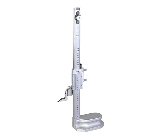
Featuring a vertical main scale column and a sliding vernier carriage, this tool holds a hardened carbide scriber. Technicians slide the carriage up and down to measure part heights or scribe exact reference lines on raw stock.
Key Operational Advantages
Adding a classic vernier height gage to your inspection station provides clear technical benefits:
High Mechanical Reliability: Operates entirely without batteries, electronics, or digital screen failures.
Carbide-Tipped Scriber: Scribes crisp, accurate layout lines directly onto hardened metal surfaces without damaging the tip.
Rigid Heavy Base: Stable cast iron or steel base prevents tipping and eliminates measuring vibration errors.
Fine Adjustment Feed: Features a micro-adjustment thumb screw to set exact vertical dimensions effortlessly.
Common Shop Floor Applications
Machinists and quality control inspectors rely on vernier height gages for critical daily tasks:
Machining Part Layout: Scribe accurate horizontal reference lines onto raw metal workpieces before milling.
Location Verification: Check hole center heights from a surface plate reference plane.
Tool Setting: Transfer precise height dimensions to cutting tools and milling fixtures.
How to Measure in 4 Simple Steps
Follow these basic steps to perform accurate vertical measurement checks:
Clean the Surface Plate: Wipe your granite plate and gage base using alcohol and lint-free cloths.
Set Initial Zero: Bring the scriber tip down to touch the surface plate and verify zero alignment.
Position the Workpiece: Slide your target part close to the gage column on the surface plate.
Read the Vernier Scale: Lower the scriber onto your test surface and read the combined scale value.
Final Thoughts
The vernier height gage remains a dependable workhorse for modern machining and metal fabrication. By delivering reliable vertical measurements without electronic dependence, this durable tool protects product quality and maintains strict shop standards.
Adjustable main vernier scale
Base fit comfortably in hand and move easily on surface plate
Large lock knobs
Fine adjustment function
Workshop Accuracy: The Machinist’s Guide to Vernier Height Gages
Achieving precise vertical dimensions and accurate layout lines presents daily challenges in modern machine shops. Relying on basic rulers or handheld calipers often leads to alignment errors on complex workpieces. A durable vernier height gage solves this measurement challenge by offering stable, precise vertical checks directly on granite surface plates.
This guide explains how integrating a vernier height gage elevates quality control across manufacturing environments.
What Is a Vernier Height Gage?
A vernier height gage is a rigid vertical measuring instrument mounted on a heavy, precision-ground base.
Featuring a vertical main scale column and a sliding vernier carriage, this tool holds a hardened carbide scriber. Technicians slide the carriage up and down to measure part heights or scribe exact reference lines on raw stock.
Key Operational Advantages
Adding a classic vernier height gage to your inspection station provides clear technical benefits:
High Mechanical Reliability: Operates entirely without batteries, electronics, or digital screen failures.
Carbide-Tipped Scriber: Scribes crisp, accurate layout lines directly onto hardened metal surfaces without damaging the tip.
Rigid Heavy Base: Stable cast iron or steel base prevents tipping and eliminates measuring vibration errors.
Fine Adjustment Feed: Features a micro-adjustment thumb screw to set exact vertical dimensions effortlessly.
Common Shop Floor Applications
Machinists and quality control inspectors rely on vernier height gages for critical daily tasks:
Machining Part Layout: Scribe accurate horizontal reference lines onto raw metal workpieces before milling.
Location Verification: Check hole center heights from a surface plate reference plane.
Tool Setting: Transfer precise height dimensions to cutting tools and milling fixtures.
How to Measure in 4 Simple Steps
Follow these basic steps to perform accurate vertical measurement checks:
Clean the Surface Plate: Wipe your granite plate and gage base using alcohol and lint-free cloths.
Set Initial Zero: Bring the scriber tip down to touch the surface plate and verify zero alignment.
Position the Workpiece: Slide your target part close to the gage column on the surface plate.
Read the Vernier Scale: Lower the scriber onto your test surface and read the combined scale value.
Final Thoughts
The vernier height gage remains a dependable workhorse for modern machining and metal fabrication. By delivering reliable vertical measurements without electronic dependence, this durable tool protects product quality and maintains strict shop standards.
Adjustable main vernier scale
Base fit comfortably in hand and move easily on surface plate
Large lock knobs
Fine adjustment function
Precision Inspection: DIAL DEPTH GAGE - Back Plunger Guide
Measuring narrow bores and recessed slots presents tough visibility challenges in machine shops. Standard depth gauges often position their dial faces awkwardly, forcing inspectors to contort their view. A specialized DIAL DEPTH GAGE - Back Plunger solves this ergonomic issue by placing the measuring spindle perpendicular to the dial face.
This guide explains how back plunger depth gages improve accuracy across compact inspection setups.
What Is a DIAL DEPTH GAGE - Back Plunger?
A back plunger depth gage is a precision metrology instrument featuring a measuring spindle mounted directly on the back of the dial housing.
Unlike standard indicators with bottom stems, the back plunger design allows the dial to face upward while the measuring probe extends downward. This layout enables clear, direct reading when inspecting tight recesses or mounting tools on leveling fixtures.
Key Operational Advantages
Choosing a back plunger depth gage offers clear practical benefits for quality inspectors:
Direct Upward Visibility: Face-up dial positioning allows effortless reading in cramped machine setups.
Compact Footprint: Mounting the spindle behind the bezel saves vertical space on surface plates.
High Measurement Sensitivity: Rack-and-pinion movement detects fine depth changes down to 0.01 mm or 0.0005 inches.
Interchangeable Rods: Extension rods adapt the tool easily to various cavity depths.
Common Workshop Applications
Machinists and quality technicians rely on back plunger depth gages for specialized tasks:
Follow these simple steps to perform accurate depth checks:
Clean the Reference Base: Wipe your reference surface and gage base with alcohol wipes.
Set Initial Zero: Press the base flat against a master reference plate and zero the bezel.
Position over Target: Insert the probe carefully into your workpiece cavity or slot.
Record the Reading: Rest the base flush on the part surface and note the needle displacement.
Final Thoughts
The DIAL DEPTH GAGE - Back Plunger resolves visibility bottlenecks in cramped measuring environments. By combining compact geometry with high accuracy, this reliable tool protects product quality and maintains strict manufacturing standards.
Easy to handle in measurement of depth
Back plunger type
with extension rod to increase the range
Precision Inspection: DIAL DEPTH GAGE - Back Plunger Guide
Measuring narrow bores and recessed slots presents tough visibility challenges in machine shops. Standard depth gauges often position their dial faces awkwardly, forcing inspectors to contort their view. A specialized DIAL DEPTH GAGE - Back Plunger solves this ergonomic issue by placing the measuring spindle perpendicular to the dial face.
This guide explains how back plunger depth gages improve accuracy across compact inspection setups.
What Is a DIAL DEPTH GAGE - Back Plunger?
A back plunger depth gage is a precision metrology instrument featuring a measuring spindle mounted directly on the back of the dial housing.
Unlike standard indicators with bottom stems, the back plunger design allows the dial to face upward while the measuring probe extends downward. This layout enables clear, direct reading when inspecting tight recesses or mounting tools on leveling fixtures.
Key Operational Advantages
Choosing a back plunger depth gage offers clear practical benefits for quality inspectors:
Direct Upward Visibility: Face-up dial positioning allows effortless reading in cramped machine setups.
Compact Footprint: Mounting the spindle behind the bezel saves vertical space on surface plates.
High Measurement Sensitivity: Rack-and-pinion movement detects fine depth changes down to 0.01 mm or 0.0005 inches.
Interchangeable Rods: Extension rods adapt the tool easily to various cavity depths.
Common Workshop Applications
Machinists and quality technicians rely on back plunger depth gages for specialized tasks:
Follow these simple steps to perform accurate depth checks:
Clean the Reference Base: Wipe your reference surface and gage base with alcohol wipes.
Set Initial Zero: Press the base flat against a master reference plate and zero the bezel.
Position over Target: Insert the probe carefully into your workpiece cavity or slot.
Record the Reading: Rest the base flush on the part surface and note the needle displacement.
Final Thoughts
The DIAL DEPTH GAGE - Back Plunger resolves visibility bottlenecks in cramped measuring environments. By combining compact geometry with high accuracy, this reliable tool protects product quality and maintains strict manufacturing standards.
Easy to handle in measurement of depth
Back plunger type
with extension rod to increase the range
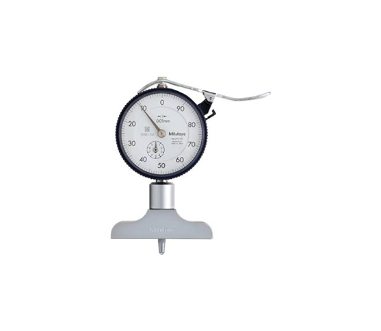
Precision Depth Measurement: DIAL DEPTH GAGE - 7 Series
Measuring hole depths and narrow steps accurately presents daily challenges on the shop floor. Handheld calipers often rock during inspection, leading to alignment errors and false readings. The DIAL DEPTH GAGE - 7 series solves this quality control challenge by offering a wide, hardened reference base for stable, highly repeatable depth measurements.
This guide explains how integrating a 7 series dial depth gage elevates metrology accuracy across your manufacturing facility.
What Is the DIAL DEPTH GAGE - 7 Series?
The 7 series is a high-precision analog depth measuring instrument manufactured by Mitutoyo.
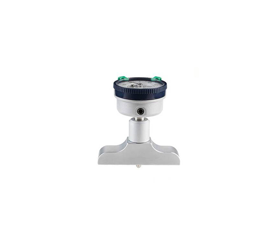
Featuring a precision dial indicator mounted onto a ground steel base, this tool measures blind hole depths, narrow slots, and shoulder steps. Technicians swap extension rods to adapt the gage for deep cavities across various workpiece dimensions effortlessly.
Key Advantages for Machinists
Upgrading to a 7 series depth gage delivers clear operational benefits for quality inspectors:
High Stability: Hardened steel base provides a flat, rigid reference surface on test parts.
Fine Measurement Resolution: Reads subtle depth variations down to 0.01 mm or 0.001 inches clearly.
Interchangeable Rods: Extension rods expand total measuring depth reach up to 210 mm.
Smooth Mechanism: Precision rack-and-pinion movement delivers immediate pointer response without binding.
Common Workshop Applications
Quality inspectors and machinists rely on 7 series depth gages for essential daily tasks:
Blind Hole Inspection: Measure exact depths of drilled and tapped blind holes accurately.
Step and Shoulder Checks: Verify vertical height gaps between parallel workpiece surfaces.
Keyway Depth Verification: Inspect internal keyway grooves and recessed slots on machined shafts.
Toolroom Metrology: Check cavity dimensions on injection molds and stamping dies.
How to Measure Depths in 4 Easy Steps
Follow these simple steps to perform accurate depth inspection checks:
Clean the Base: Wipe your reference surface and gage base with alcohol wipes.
Set Initial Zero: Rest the base on a master surface plate and zero the bezel pointer.
Insert the Contact Point: Lower the measuring probe carefully into your workpiece cavity.
Record the Reading: Hold the base flush against the part and note the dial displacement.
Final Thoughts
The DIAL DEPTH GAGE - 7 series turns complex cavity checks into fast, repeatable inspection tasks. By eliminating measurement wobble, this reliable metrology tool protects product quality and maintains strict manufacturing standards.
Easy to handle in measurement of depth
with extension rod to increase the range
Precision Depth Measurement: DIAL DEPTH GAGE - 7 Series
Measuring hole depths and narrow steps accurately presents daily challenges on the shop floor. Handheld calipers often rock during inspection, leading to alignment errors and false readings. The DIAL DEPTH GAGE - 7 series solves this quality control challenge by offering a wide, hardened reference base for stable, highly repeatable depth measurements.
This guide explains how integrating a 7 series dial depth gage elevates metrology accuracy across your manufacturing facility.
What Is the DIAL DEPTH GAGE - 7 Series?
The 7 series is a high-precision analog depth measuring instrument manufactured by Mitutoyo.
Featuring a precision dial indicator mounted onto a ground steel base, this tool measures blind hole depths, narrow slots, and shoulder steps. Technicians swap extension rods to adapt the gage for deep cavities across various workpiece dimensions effortlessly.
Key Advantages for Machinists
Upgrading to a 7 series depth gage delivers clear operational benefits for quality inspectors:
High Stability: Hardened steel base provides a flat, rigid reference surface on test parts.
Fine Measurement Resolution: Reads subtle depth variations down to 0.01 mm or 0.001 inches clearly.
Interchangeable Rods: Extension rods expand total measuring depth reach up to 210 mm.
Smooth Mechanism: Precision rack-and-pinion movement delivers immediate pointer response without binding.
Common Workshop Applications
Quality inspectors and machinists rely on 7 series depth gages for essential daily tasks:
Blind Hole Inspection: Measure exact depths of drilled and tapped blind holes accurately.
Step and Shoulder Checks: Verify vertical height gaps between parallel workpiece surfaces.
Keyway Depth Verification: Inspect internal keyway grooves and recessed slots on machined shafts.
Toolroom Metrology: Check cavity dimensions on injection molds and stamping dies.
How to Measure Depths in 4 Easy Steps
Follow these simple steps to perform accurate depth inspection checks:
Clean the Base: Wipe your reference surface and gage base with alcohol wipes.
Set Initial Zero: Rest the base on a master surface plate and zero the bezel pointer.
Insert the Contact Point: Lower the measuring probe carefully into your workpiece cavity.
Record the Reading: Hold the base flush against the part and note the dial displacement.
Final Thoughts
The DIAL DEPTH GAGE - 7 series turns complex cavity checks into fast, repeatable inspection tasks. By eliminating measurement wobble, this reliable metrology tool protects product quality and maintains strict manufacturing standards.
Easy to handle in measurement of depth
with extension rod to increase the range
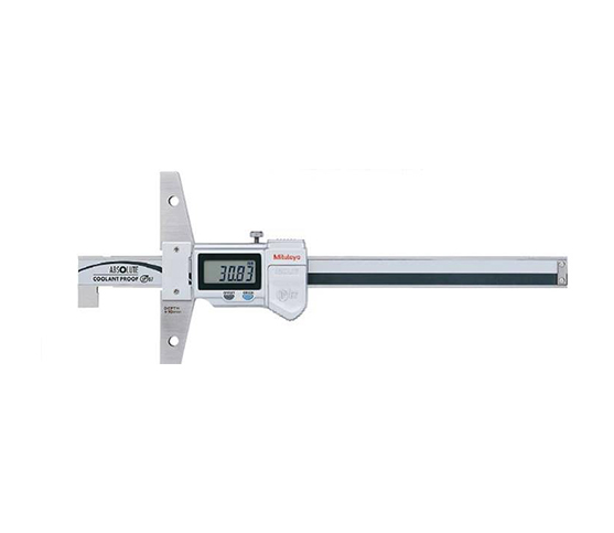
Mastering the Digimatic Depth Gage: Precision Depth Measurement Made Simple
Precision manufacturing requires total accuracy across every component dimension. Measuring blind holes, narrow slots, keyways, and step heights often creates measurement challenges. Traditional vernier tools take time to read and leave room for human error. A Digimatic Depth Gage solves this issue by offering quick, high-precision digital readings for modern quality control.
What Is a Digimatic Depth Gage?
A digimatic depth gage is an advanced digital measuring tool. It features a wide, flat base connected to a smooth sliding depth rod or blade. Operators place the ground base firmly over the reference surface and extend the rod into the cavity. An electronic encoder calculates the distance instantly, displaying precise numbers on a clear LCD screen.
Major Advantages for Quality Control
Upgrading to a digital depth instrument offers immediate production benefits:
Instant Digital Readings: High-contrast LCD displays show values clearly, reducing reading mistakes on the shop floor.
Data Output Capability: Most digital models connect directly to SPC data collection systems for seamless quality logging.
Zero-Setting Flexibility: Inspectors can set a zero point at any location to measure relative step differences effortlessly.
Unit Switching: Operators toggle between inches and millimeters instantly with a single button press.
How to Use a Digimatic Depth Gage Properly
Achieve accurate depth readings by following these key steps:
Clean All Contact Points: Wipe the reference base, depth rod, and workpiece free of dust, oil, and metal burrs.
Set the Zero Baseline: Press the base against a precision surface plate, extend the rod fully, and press the zero button.
Seat the Base Firmly: Hold the base flat against your workpiece reference plane with steady downward pressure.
Extend and Lock: Slide the depth rod until it touches the bottom of the cavity, then lock the thumb screw before recording your data.
Care and Maintenance Practices
Keep your digital gage accurate with simple maintenance habits. Wipe the beam with a dry cloth after each shift, and avoid harsh solvents. Remove the battery if you store the unit for long periods. Store the gage in its protective case to prevent bending the depth rod.
A reliable Digimatic Depth Gage optimizes inspection workflows, cuts quality control time, and guarantees tight tolerance compliance across every project.
The hook sharped allow depth and thickness measurements
Base 250x10mm for range 600 to 1000mm
Base 100x6.5mm for range 0 to 300mm
Mastering the Digimatic Depth Gage: Precision Depth Measurement Made Simple
Precision manufacturing requires total accuracy across every component dimension. Measuring blind holes, narrow slots, keyways, and step heights often creates measurement challenges. Traditional vernier tools take time to read and leave room for human error. A Digimatic Depth Gage solves this issue by offering quick, high-precision digital readings for modern quality control.
What Is a Digimatic Depth Gage?
A digimatic depth gage is an advanced digital measuring tool. It features a wide, flat base connected to a smooth sliding depth rod or blade. Operators place the ground base firmly over the reference surface and extend the rod into the cavity. An electronic encoder calculates the distance instantly, displaying precise numbers on a clear LCD screen.
Major Advantages for Quality Control
Upgrading to a digital depth instrument offers immediate production benefits:
Instant Digital Readings: High-contrast LCD displays show values clearly, reducing reading mistakes on the shop floor.
Data Output Capability: Most digital models connect directly to SPC data collection systems for seamless quality logging.
Zero-Setting Flexibility: Inspectors can set a zero point at any location to measure relative step differences effortlessly.
Unit Switching: Operators toggle between inches and millimeters instantly with a single button press.
How to Use a Digimatic Depth Gage Properly
Achieve accurate depth readings by following these key steps:
Clean All Contact Points: Wipe the reference base, depth rod, and workpiece free of dust, oil, and metal burrs.
Set the Zero Baseline: Press the base against a precision surface plate, extend the rod fully, and press the zero button.
Seat the Base Firmly: Hold the base flat against your workpiece reference plane with steady downward pressure.
Extend and Lock: Slide the depth rod until it touches the bottom of the cavity, then lock the thumb screw before recording your data.
Care and Maintenance Practices
Keep your digital gage accurate with simple maintenance habits. Wipe the beam with a dry cloth after each shift, and avoid harsh solvents. Remove the battery if you store the unit for long periods. Store the gage in its protective case to prevent bending the depth rod.
A reliable Digimatic Depth Gage optimizes inspection workflows, cuts quality control time, and guarantees tight tolerance compliance across every project.
The hook sharped allow depth and thickness measurements
Base 250x10mm for range 600 to 1000mm
Base 100x6.5mm for range 0 to 300mm